Inside Your Freezer Floor Control Panel
A tour of the PLC control and monitoring panel — and how it operates day to day
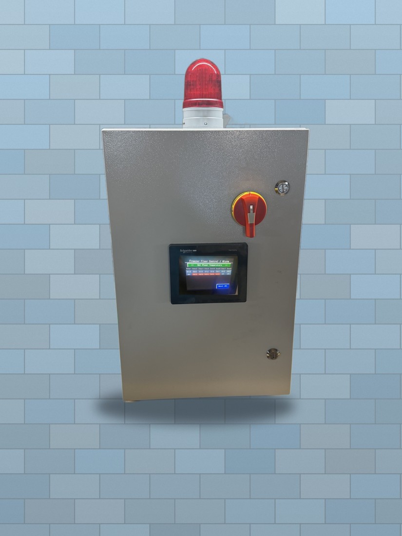
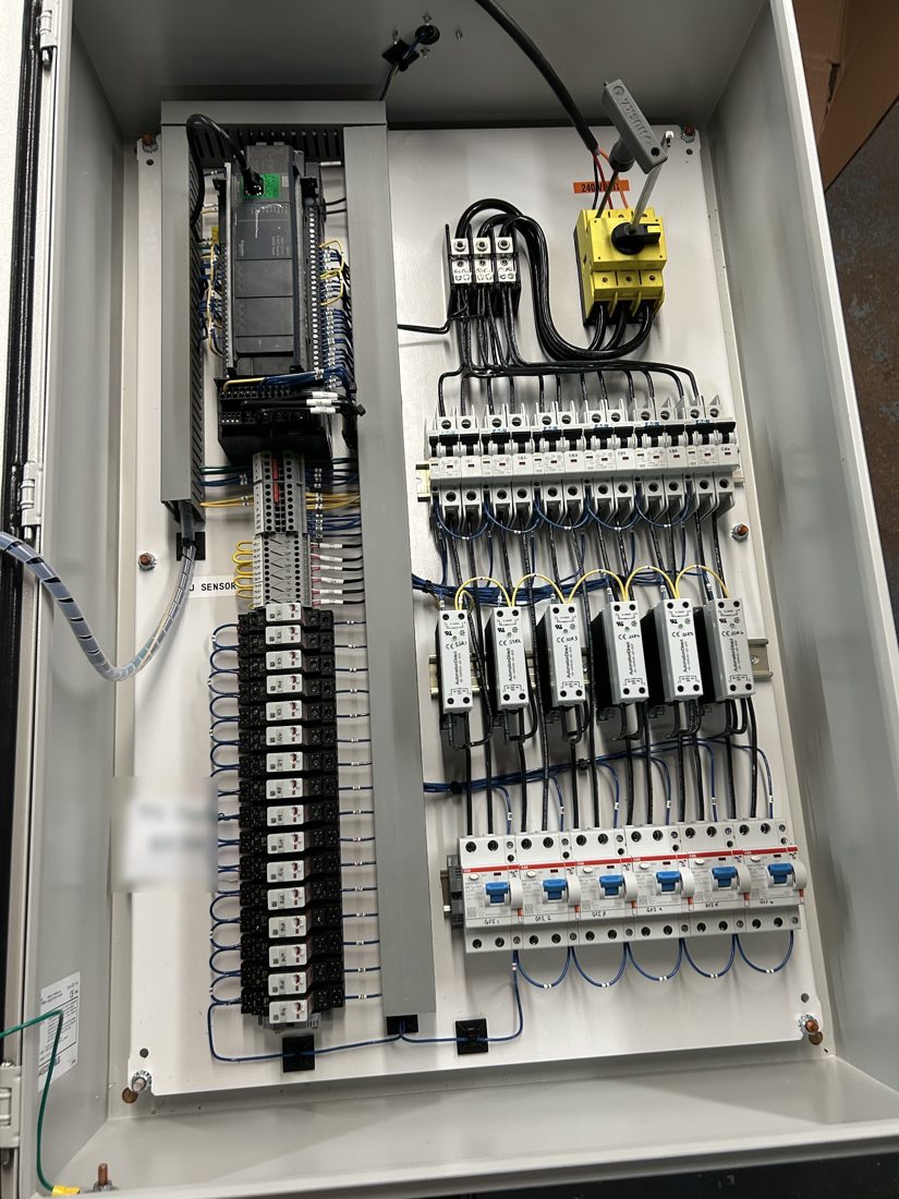
Every Thermalinc electric heat cable system is run by a custom-built PLC control panel — not just a switch and a breaker, but a system that protects every circuit individually, watches the floor directly, and keeps a permanent record of anything that happens. Below is a look inside a couple of real panels we've built, and a plain-language guide to what each part does and how to read it day to day.
What's Inside the Panel
How the System Operates
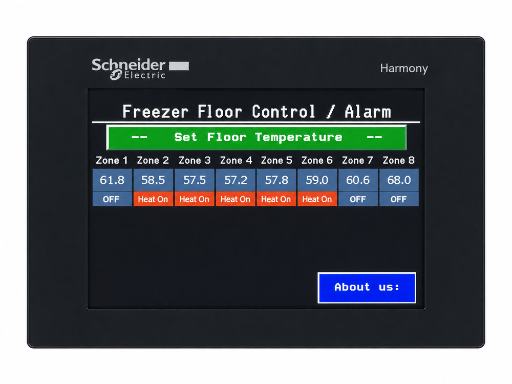
On startup, the PLC brings up the display and begins reading every zone's floor temperature and circuit status. In normal operation, the display shows each zone's current temperature against its setpoint, and the PLC cycles the solid-state relays on and off as needed to hold that setpoint — you don't have to do anything. The panel is doing its job quietly in the background.
If a circuit is off because it isn't currently calling for heat, that's normal — it isn't a fault. The display distinguishes between a circuit that's simply idle and a circuit that has actually failed.
If an Alarm Sounds
The panel is built to make a fault impossible to miss, and impossible to accidentally ignore.
- The horn sounds and the stack light turns on. The 98 dB horn and the red stack light activate together the moment a fault is detected — low floor temperature, a tripped GFI, a failed sensor, or a circuit that isn't energizing correctly.
- Check the display. The color screen identifies which zone or circuit triggered the alarm and when. A brief troubleshooting guide is built into the fault history to point you toward the likely cause.
- Silence the horn. Acknowledging the alarm silences the horn, but the stack light stays lit for as long as the fault condition still exists — a quiet horn is never mistaken for a resolved problem.
- Follow the troubleshooting guide. Most faults — a tripped breaker or GFI, for example — are a simple reset once the underlying cause is corrected. The fault log keeps a permanent record of what happened and where, so nothing has to be diagnosed from memory.
- Call us if you're not sure. If the fault doesn't clear, or you're not certain what you're looking at, contact Thermal Equipment Sales Co. — have the zone/circuit number from the display ready.
Panel Components, Plain-Language
| Component | What it does |
|---|---|
| Main disconnect | A single point electrical connection for the system, with lockout/tagout (LOTO), for safe shutdown of the whole panel for service. |
| Circuit breaker (per circuit) | Overcurrent protection isolated to one circuit; a fault on one zone never affects the others. |
| GFI breaker (per circuit) | Ground-fault protection isolated to one circuit, independently monitored by the PLC. |
| Solid-state relay (SSR) | Switches each heat cable circuit on and off under PLC control — no mechanical contactor to wear out. |
| Far-end voltage sensing | Confirms actual cable energization at the far end of every run, catching a failed-shorted circuit as well as a failed-open or cable/connection fault. |
| PLC | The controller that reads every sensor, drives every relay, and holds each zone at its setpoint. |
| Color display (HMI) | Shows real-time zone temperatures, circuit status, and lets you review fault and temperature history right at the panel. |
| 98 dB horn | Sounds immediately on any fault so it's noticed in an active facility. |
| Stack light | Red, and stays lit after the horn is silenced for as long as the fault persists. |
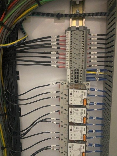
| Terminal blocks / monitor relays | Terminate the end-of-run monitor and temperature sensor wiring for every zone, feeding status back to the PLC. |
See our complete Controls and Monitoring section for the full feature list, or read the full comparison against hydronic glycol systems to see why this control architecture is part of what sets Thermalinc's electric heat cable system apart.