How a Frost Heave Floor Is Designed
Heat cable, laid to heat the ground — not the floor
Heat cable frost heave systems provide better monitoring and control, with less maintenance than air or glycol systems. Self-regulating heat cable automatically adjusts wattage as temperatures change, always providing the correct output to maintain 50°F.
The cable is designed to heat the ground — not the freezer floor itself. Freezers pull heat out of the ground below them continuously; the cable simply replaces what's being pulled out, holding the subgrade above freezing indefinitely.
How the Freezer Floor Heating System Is Installed
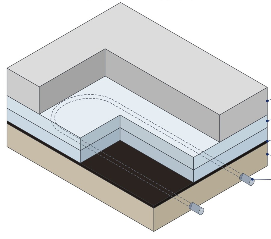
- Subgrade / base A prepared base or hard-packed substrate supports the heating system.
- Heating conduit 3/4" rigid conduit is installed within the substrate according to the layout, backfilled with aggregate or a mud slab — rock, gravel, sand, or any non‑insulating fill material — with a minimum 1" between the conduit and insulation.
- Heat cable Self-regulating electric heat cable runs through the conduit, providing heat to the subgrade and automatically adjusting wattage as temperatures change.
- Insulation 2 layers of high-density insulation, joints staggered, installed above the heated substrate to reduce heat loss toward the freezer.
- Vapor barrier Minimum 6 mil vapor barrier, joints overlapped 12".
- Top slab Install top slab per structural requirements.
Complete Freezer Floor Heating System Design
Thermalinc does considerably more than sell heat cable. From the initial layout through the finished control panel, we provide the design work a project actually needs:
- Heat cable sizing
- Conduit layout
- Cable spacing recommendations
- Electrical load calculations
- Circuit layout
- Temperature sensor placement
- Control panel design
- GFI/GFEP protection
- Alarm and monitoring
- Wiring diagrams
- Installation documentation
- Application assistance
Heat Load Sizing
Approximate watts per linear foot of cable, by freezer temperature, insulation thickness, and cable spacing. Actual heat load is calculated per project.
| Freezer Temp | Watts @ 2 ft | Watts @ 3 ft | Watts @ 4 ft |
|---|---|---|---|
| −40°F | 6.4 | 7.3 | 9.1 |
| −20°F | 4.1 | 5.1 | 7.0 |
| −10°F | 3.6 | 4.3 | 5.5 |
| 0°F | 3.2 | 4.0 | 4.8 |
| 10°F | 2.7 | 3.0 | 3.4 |
| Freezer Temp | Watts @ 2 ft | Watts @ 3 ft | Watts @ 4 ft |
|---|---|---|---|
| −40°F | 3.9 | 5.2 | 7.0 |
| −20°F | 3.2 | 3.7 | 4.9 |
| −10°F | 2.7 | 3.0 | 4.0 |
| 0°F | 2.3 | 2.7 | 3.2 |
| 10°F | 1.8 | 2.1 | 2.4 |
Spacing of 5 to 8 feet, sometimes used in the industry to reduce cable footage and cost, but does not transfer enough heat to prevent striping between runs — and has been linked to cracked, heaved floors and significant structural damage. Proper spacing is a heat transfer and heat loss calculation, not just a watts-per-foot or watts-loss consideration.
See our full side-by-side comparison — system components, failure points for each approach, and the protection and monitoring built into Thermalinc's electric heat cable system. Read the full comparison →
This is one piece of the full freezer floor frost heave prevention system. Back to Freezer Floor Frost Heave Prevention →